Overview
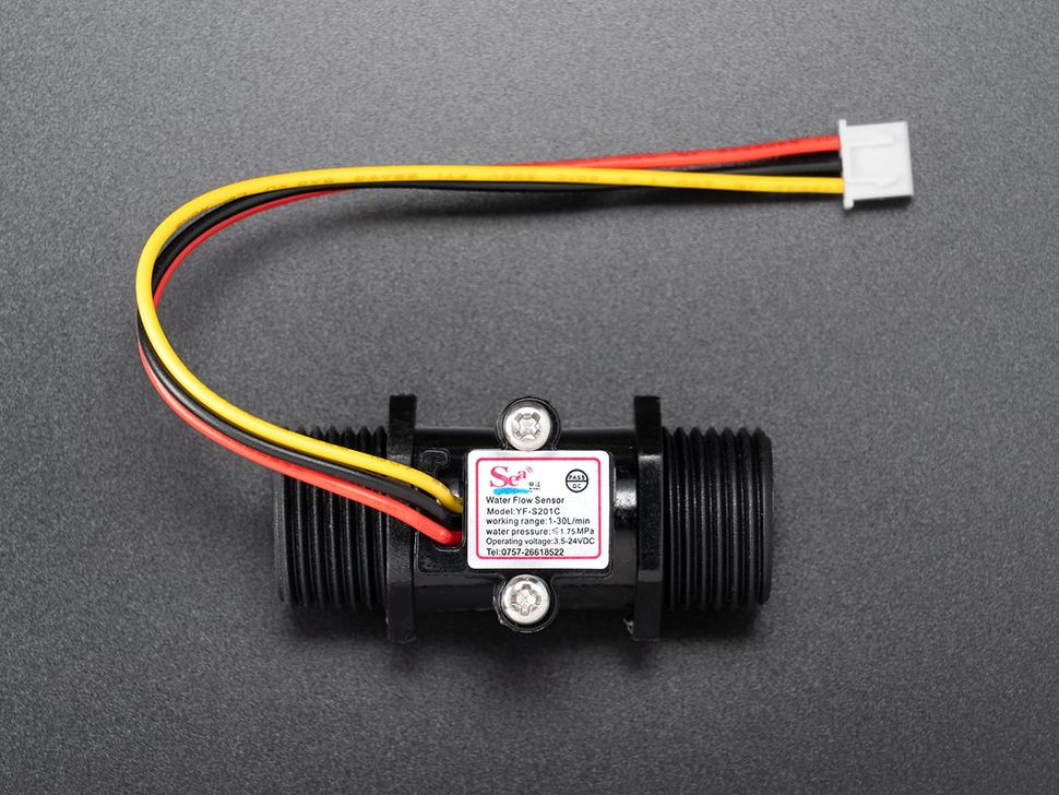
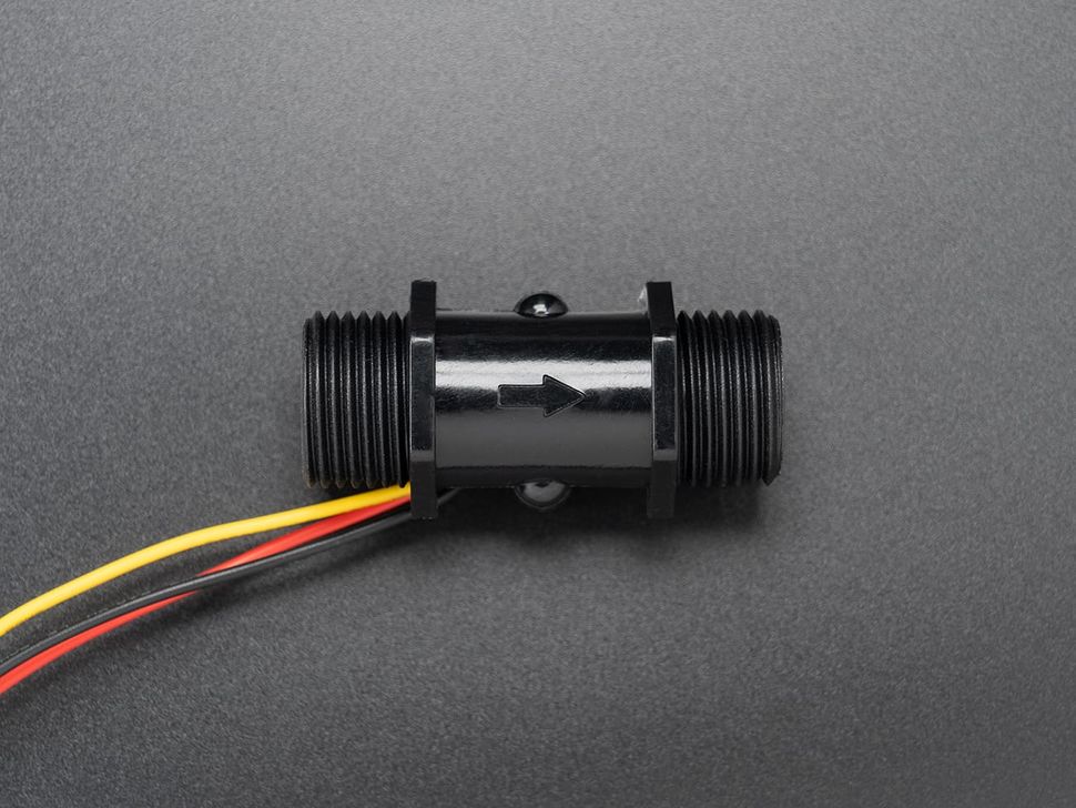
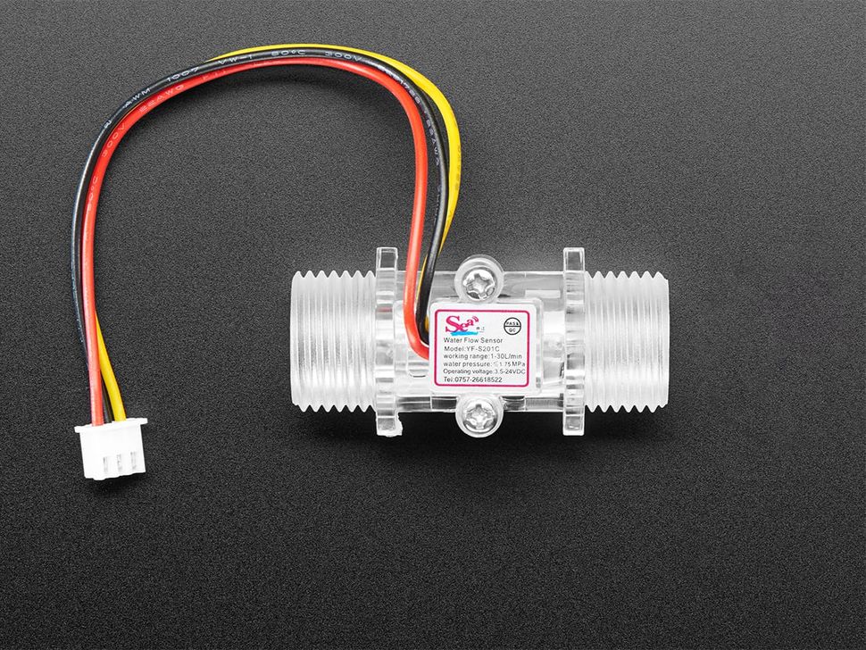
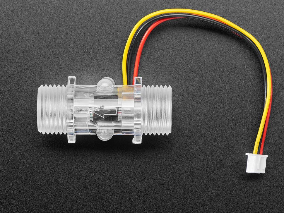
The YF-S201C is a water flow sensor that measures liquid flow rates. It consists of a plastic housing, a rotating impeller, and a Hall effect sensor. It has a flow rate of 1 to 30 Litres per minute and can handle maximum pressure of 1.75 megapascals.
How it works?
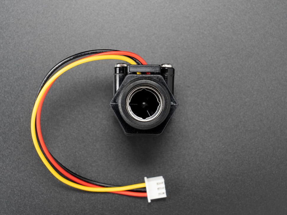
It has a rotor (a.k.a impeller) inside and as the water flows through the sensor, it pushes against the blades of the rotor causing it to spin which has a magnet attached to it. The faster the water flows, the faster the rotor spins along with the magnets. These rotations are sensed using a hall efect sensor which can detect the magnetic field and is positioned near the rotor.
As the magnet on the rotor spins past the Hall effect sensor, it creates a disruption in the magnetic field. The Hall effect sensor detects this change and outputs an electrical signal, typically a pulse. The number of pulses generated by the sensor is directly related to the speed of the rotor, which in turn, is related to the flow rate of the water.
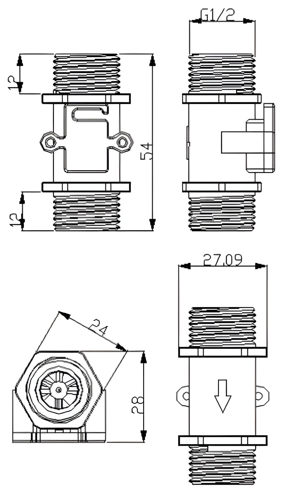
Dimensions
Dimension and physical characteristics of the YF-S201C water flow sensor.
Specifications
Specifications for YF-S201C water flow sensor.
| Model | YF-S201C |
| Operating Voltage | 3.5V to 24V DC |
| Max. Operating Current | 15mA @ 5V DC |
| Operating Flow Rate | 1 to 30 L/min |
| Operating Temperature | -25°C to 80°C |
| Operating Humidity Range | 25% to 95%RH |
| Max. Water Pressure | 1.75 MPa |
| Output Duty Cycle | 50% ±10% |
| Output Rise Time | 0.04 us |
| Output Fall Time | 0.018 us |
| Flow Rate Pulse | Pulse Frequency = 7.5 x Q Q = Flow Rate L/min |
| External Threads | 1/2 inch |
| Durability | 300,000 cycles |
Pinout
YF-S201C Water flow sensor pinout and wire color coding.
| No. | Pins | Color |
| 1 | 5V - 24V DC | Red |
| 2 | GND | Black |
| 3 | Pulse Output | Yellow |
Connections & Code
Connection
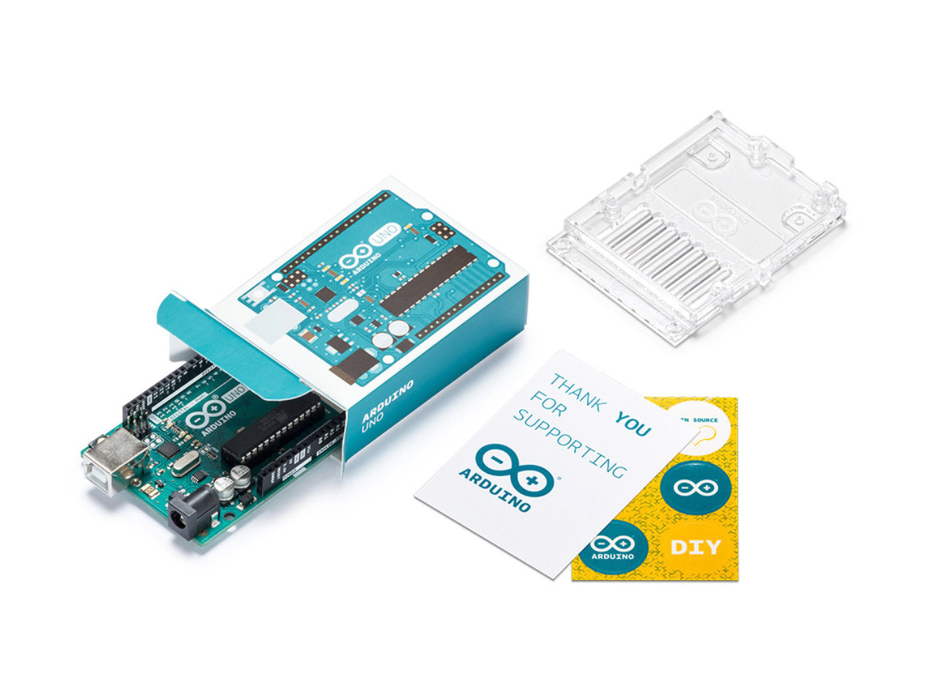
- VIN (Red): You may connect this to 5V pin on arduino UNO but we recommend to connect it to an external power supply of 5V DC
- GND (Black): Connect to GND. Make sure you connect all ground pins together. If you are using an external power supply connect the power supply ground to aduino UNO GND.
- Pulse Output (Yellow): Connect to digital pin 2.
Code
Arduino UNO code for water flow sensor.
No external libraries are needed for this basic code.
#define flowPin 2  // Define the digital pin connected to the flow sensor

volatile int flow_count = 0; // Counts the number of pulses from the sensor

void setup() {
  Serial.begin(9600);        // Initialize serial communication for debugging
  pinMode(flowPin, INPUT);    // Set the flow sensor pin as input
  attachInterrupt(digitalPinToInterrupt(flowPin), flowInterrupt, RISING);
  // Enable interrupt on rising edge (each pulse)
}

void loop() {
  unsigned long currentMillis = millis();
  static unsigned long previousMillis = 0; // Stores time of last interrupt

  // Calculate flow rate every 1 second
  if (currentMillis - previousMillis >= 1000) {
    float flowRate = (flow_count * 60.0) / (currentMillis - previousMillis);  // Flow rate in pulses per minute
    Serial.print("Flow Rate: ");
    Serial.print(flowRate);
    Serial.println(" pulses per minute");
    flow_count = 0; // Reset counter for next measurement
    previousMillis = currentMillis;
  }
}

void flowInterrupt() {
  flow_count++; // Increment pulse counter on interrupt
}
Opps
Sorry, it looks like some products are not available in selected quantity.
